
All-solid-state MXene-based flexible zinc ion microcapacitor array: laser direct writing + in-situ annealing

Compared with traditional supercapacitors, zinc ion hybrid supercapacitors have higher energy density and are a promising energy storage device. The realization of miniaturization, patterning and flexibility of zinc ion capacitors without affecting electrochemical performance is of great significance for expanding its application in the field of wearable integrated electronics. Cathode functional materials are one of the key factors affecting the electrochemical performance of zinc ion microcapacitors (zinc microcapacitors). Choosing a suitable cathode material can effectively increase the energy density of zinc microcapacitors. Ti₃C₂Tₓ MXene electrode material has excellent electrical conductivity, unique two-dimensional layered structure and good mechanical stability. It has shown great potential in the design of zinc microcapacitors, but it is still facing long-term cycle stability and high-rate stability. challenge.
Highlights of this article
1. Using a large piece of Ti₃C₂Tₓ MXene as the current collector and a small piece of Ti₃C₂Tₓ as the cathode material, the flexible zinc microcapacitor array is prepared by the laser direct writing method. After in-situ annealing treatment, it can stably cycle charge and discharge 50,000 times.
2. The prepared single zinc microcapacitor can drive the digital timer for tens of minutes in the bent state. The assembled flexible zinc microcapacitor array can still light up the flexible LED display with the "TiC" logo in the state of twisting, curling and winding, indicating that flexible zinc ion hybrid capacitors have huge application potential in the field of wearable integrated electronics .
brief introduction
Professor Chen Di, University of Science and Technology Beijing, Researcher Shen Guozhen, Institute of Semiconductors, Chinese Academy of Sciences, etc.In this paper, a simple and feasible laser direct writing method is proposed to prepare a flexible zinc microcapacitor array based on Ti₃C₂Tₓ MXene, and the device is annealed in situ to improve its cycle stability. Tests have shown that even after 50,000 charge-discharge cycles, the device still has a capacitance retention rate of more than 80% and a high rate stability.
In addition, this paper also studied the influence of the thickness of the cathode material of Ti₃C₂Tₓ on the electrochemical performance of zinc microcapacitors. By testing the performance of devices with different thicknesses, the optimal thickness was found to be 0.851 μm. At the same time, the flexible zinc microcapacitor based on Ti₃C₂Tₓ MXene has good mechanical stability. In different bending states, a single device can drive a digital timer. The assembled flexible zinc microcapacitor array can easily light up the flexible LED display with the "TiC" logo under twisting, crimping and winding conditions, indicating that flexible zinc microcapacitors have huge application potential in the field of wearable integrated electronics.
Graphic guide
I Material characterization
Ti₃C₂Tₓ MXene material is prepared by selective etching of the Al atomic layer in the MAX phase, and its morphology and structure are shown in Figure 1a~e. After Ti₃AlC₂ was etched by mixed acid, the material showed a classic organ-like structure (Figure 1a). Figure 1b-d are the SEM and TEM images of a single layer of Ti₃C₂Tₓ after intercalation. Figure 1e shows the XRD patterns of multi-layer and few-layer Ti₃C₂Tₓ films. After intercalation, the characteristic peak of 002 shifts to the left, about 6.7°. Figure 1f shows the specific process flow of assembling a flexible zinc microcapacitor array based on Ti₃C₂Tₓ MXene on a flexible PI substrate by laser direct writing. The 4 groups of zinc microcapacitor components can be directly attached to the nail (Figure 1g, right), showing its miniature and wearable characteristics, which is beneficial to be applied to integrated flexible electronic products.

Figure 1. The morphology and structure of the synthesized Ti₃C₂Tₓ MXene material and the preparation process of the zinc microcapacitor array. (a) SEM image of multilayer Ti₃C₂Tₓ MXene. (b) SEM image of Ti₃C₂Tₓ MXene after intercalation. (c) Distribution map of Ti and C elements. (d) TEM image of Ti₃C₂Tₓ MXene. (e) XRD patterns of multilayer and single-layer Ti₃C₂Tₓ MXene. (f) Schematic diagram of laser direct writing process. (g) Photo of Ti₃C₂Tₓ MXene supernatant and display image of array device.
II Device preparationFigure 2a confirms that the laser direct writing process can prepare various preset patterns of MXene electrodes on different substrates. For example, "USTB, CAS" is etched on a transparent PET substrate (size 3*3 cm). , Flextronics, Institute of semiconductor", cartoon patterns and arrayed patterns, indicating the possibility of custom-designed flexible zinc microcapacitor arrays according to actual needs. The microscope image of a zinc microcapacitor with a concentric structure (Figure 2b) shows that the gap between the positive and negative electrodes of the assembled device is 100 microns. In order to improve the utilization of Ti₃C₂Tₓ electrode material, Figure 2c discusses the optimal electrode thickness. The results show that as the number of Ti₃C₂Tₓ layers increases, the area ratio of the prepared zinc microcapacitors first increases and then decreases, and the best average thickness is about 0.851 microns.
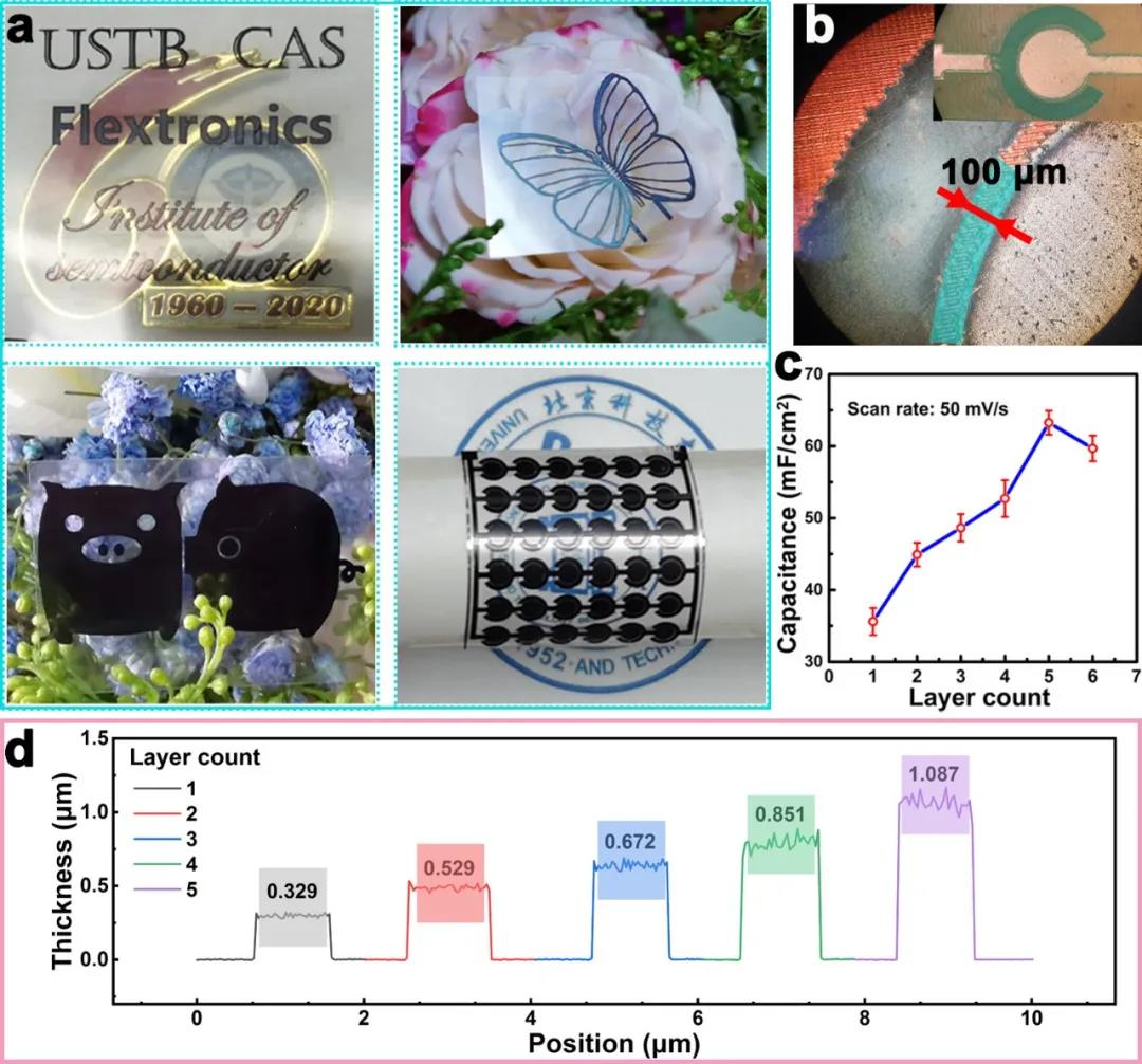
Figure 2. Design of zinc microcapacitors with different electrode structures and testing of optimal electrode thickness. (a) Zinc microcapacitors with different characters and different shapes. (b) A microscope image of a zinc microcapacitor with a concentric circle structure. (c) The specific capacitance of zinc microcapacitor varies with the number of electrode material layers. (d) The thickness of the electrode material varies with the number of layers.
III Electrochemical performance analysisFigure 3 systematically shows the electrochemical performance of the concentric structure Ti₃C₂Tₓ-MXene-based flexible zinc microcapacitors. Before annealing, the CV curve of the zinc microcapacitor (Figure 3a) is quasi-rectangular at low scanning speed, and redox peaks appear, corresponding to the process of insertion and extraction of zinc ions. But the unannealed device after 5000 charge and discharge cycles, the capacitance value is only 54.7% of the initial value. Therefore, we annealed the microcapacitor device in Ar gas at 300°C for 30 minutes to remove the oxygen-containing functional groups on the surface and improve the cycle stability of the device. The CV curve and GCD curve of the device after annealing are very similar to those before annealing, indicating that the heat treatment does not damage the structure of Ti₃C₂Tₓ. In order to explore the diffusion kinetics of zinc microcapacitors after annealing, Figure 3b, c provides the capacitance contribution and diffusion contribution diagrams of the device. According to the CV curve, when the scan rate is 10 mV/s, the area specific capacitance is 72.02 mF/cm2 and the volume specific capacitance is 662.53 F/cm3, as shown in Figure 3e. Compared with other types of microcapacitors, our device also has higher energy and power density (Figure 3f). When the energy density is 0.02 mWh/cm2 (0.18 mWh/cm3), the corresponding power density is 0.50 mW/cm2 ( 0.024.63 mWh/cm3). In order to highlight the stability of the device after annealing (Figure 3g), we performed 50,000 continuous constant current charge and discharge cycles on the device. The results showed that the capacitance of the device remained above 80% of the initial value, which can be clearly seen from the figure. To the activation process of the device. This is caused by the removal of oxygen-containing functional groups on the surface of the Ti₃C₂Tₓ structure and the micropores formed during the annealing process.

Figure 3. Electrochemical performance of Ti₃C₂Tₓ-MXene-based flexible zinc microcapacitor with concentric circle structure. (a) Cyclic voltammetry (CV) curves of microcapacitors without annealing treatment at different scanning speeds. (b) Capacitance and diffusion efficiency of zinc microcapacitors at a scan rate of 50 mV/s after in-situ annealing. (c) The capacitance and diffusion contribution ratio of in-situ annealed zinc microcapacitors at different scan rates. (d) The constant current charge and discharge (GCD) curves of the device at different current densities after annealing. (e) The change of area specific capacitance with scan rate. (f) Comparison chart of areal energy density and power density. (g) Cycle stability test chart.
IV Research on charge storage mechanism
In order to study the charge storage mechanism of flexible zinc microcapacitors based on Ti₃C₂Tₓ MXene, we provide a schematic diagram of the mechanism, as shown in Figure 4a. During the discharge process, Zn transforms into Zn2⁺, moves from the negative electrode to the positive electrode, and then is inserted between Ti₃C₂Tₓ layers or adsorbed on the surface of Ti₃C₂Tₓ. When discharging, the process is reverse to the above process. This mechanism is also confirmed by the semi-in-situ scanning electron microscope (SEM) Zn element mapping and the shift and regression of the (002) characteristic peak in the X-ray diffraction (XRD) spectrum (Figure 4b-f). This reversible charging and discharging process ensures excellent cycle stability of the assembled device.

Figure 4. Mechanism study of zinc microcapacitors. (a) Schematic diagram of the discharge/charge process. (b) SEM image of Ti₃C₂Tₓ-MXene electrode material after charging. (c) The corresponding Zn element mapping in the electrode material. (d-f) In-situ XRD patterns of electrode materials during charge and discharge.
V Flexibility test and applicationDue to the flexible PI substrate and solid PVA/ZnCl₂ gel electrolyte used in assembling the device, the prepared flexible zinc microcapacitor based on Ti₃C₂Tₓ MXene has superior mechanical stability. Under different bending angles and thousands of bending times (Figure 5a-d), the CV curve and capacity of the device remain unchanged. In order to meet the needs of different electrical appliances, we can connect multiple devices in series or in parallel to output different voltages and energy densities, as shown in Figure 5e. Figure 5f proves that the prepared flexible zinc microcapacitor array can still light up the flexible LED display with the "TiC" logo even in the state of twisting, crimping and winding.

Figure 5. Mechanical stability test and application demonstration of zinc microcapacitors. (a) CV curves of flexible zinc microcapacitors in different bending states. (b) The area-to-capacitance change of flexible zinc microcapacitors under different current densities and bending times. (c) The actual photo of a single zinc microcapacitor driven digital timer in the bent state. (d) The change curve of area-to-capacitance of flexible zinc microcapacitors under multiple bending cycles. (e) CV curves of devices in different series and parallel connections. (f) The flexible zinc microcapacitor array lights up the LED flexible display.
Written by: original author
Editor: Nawei Express (English) Editorial Department
This information is sourced from the Internet for academic exchanges. If there is any infringement, please contact us to delete it immediately
+86-18915413828(WhatsApp&WeChat)
Previous: Single crystal perovsk